Timetable and Work Packages
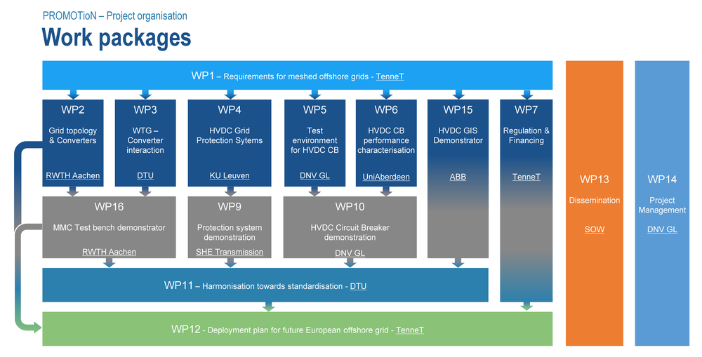
The PROMOTioN project runs over a period of four years. The project is organised in a total of 16 work packages (WP‘s), which are closely interlinked. Laying the foundation by identifying the requirements for meshed offshore grids, WP 1 commenced with the project's kick-off. WP 2-7 built upon the findings of WP 1 with the implementation of requirements for the project and an examination of specific technological issues in detail. These range from grid topology to grid protection systems (WP 2-6) as well as regulatory aspects and financing (WP 7). The results of the work in WPs 2-6 provide the foundation for WPs 9-10, 15 & 16 , who implement demonstrator and pilot facilities. WP 11 addresses questions of harmonization towards standardization. The results from WP 7 and 11 will jointly determine the development of a final deployment plan for the future meshed HVDC offshore grid. The project is flanked by WP 13 and 14, which have the task of dissemination (13) and overall project management (14).
Work package 8, that was meant to realise a full-scale demonstrator of a diode rectifier unit (DRU) based wind farm export solution at the Klim wind farm in Denmark, was prematurely terminated for technical reasons. Siemens is continuing to develop the concept towards technical maturity. PROMOTioN continues to consider the DRU as a potentially cost-saving technology for future offshore wind farm electricity export solutions. The grid integration and control of the concept is continued to be studied in work packages 2 and 3. A small-scale demonstrator is included in the MMC test bench in work package 16.
WP 1 – Requirements for meshed offshore grids
Work package 1 worked on defining the requirements and a common starting point for the project, which in itself creates few newsworthy events. However, the work proved very valuable for the execution of the project itself. The PROMOTioN project is a multidisciplinary project with a large number of partners. WP 1's main contribution is to bring together all these disciplines and different organizations and develop a shared understanding of the complexities of developing a meshed DC grid offshore. As all other work packages that started in year 1 had a smaller scope (e.g. focusing on particular parts such as DC circuit breakers, DC circuit breaker testing, protection, finance & regulation etc.), WP 1 was the place to discuss the overall view and the complexities of putting everything together. Through enabling these discussions WP 1 laid important groundwork for the PROMOTioN project as a whole and particularly the outcomes that will emerge towards the end of the project.
The first deliverable (D1.1) was a qualitative set of requirements for meshed offshore grids. Additionally WP1 produced a literature review (D1.3) to harvest the knowledge that had been gathered by other studies, and collected lessons learned from real life projects (D1.2). Jointly, these tasks ensured an optimal absorption of existing meshed offshore grid knowledge into the PROMOTioN project and its consortium. With this data, WP1 delivered preliminary grid topologies, supported by a simplified Cost Benefit Analysis (D1.4). These basic topologies were not intended as final grid structures, but as common test-topologies, which could be used for modelling purposes throughout the project. Furthermore, this work package delivered a starting list of quantified requirements. These requirements were also not set in stone, but are used as a common starting ground (D1.5). After the first two years of the project, WP1 has ended with a completely revised Quantification List (D1.7).
Download Deliverable 1.3: Synthesis of available studies on offshore meshed HVDC grids (PDF 4.0 MB)
Download Deliverable 1.4: Report with reference scenario and related offshore meshed HVDC grid topology (PDF 1.0 MB)
Download Deliverable 1.5: Quantification of requirements (PDF 2 MB)
Download Deliverable 1.6: Draft roadmap and reference offshore grid expansion plan (PDF 6 MB)
WP2 – Grid Topology & Converters
The overall objective is to perform a trade-off analysis and compare different topologies using complex simulation analysis. Interoperability, specifically of diode rectifiers and converters, is investigated by running steady-state, dynamic and transient simulations, thus demonstrating the functionality of these topologies. The results on interoperability as well as the control of converters and diode rectifiers, both during normal operation and fault scenarios, are reported and guide the definition of requirements for a full scale commercial application in WP 12. In addition, the measured effect of different offshore topologies on the onshore AC grid (e.g. frequency stability) contribute to WP12 in the same manner. Furthermore, WP 2 serves as direct input for WP 11 in order to preserve a close link to current harmonization activities and strongly interacts with WP 3 via joint studies.
WP3 – Wind Turbine – Converter Interaction
The main objective of WP 3 is to identify and specify appropriate analyses and to demonstrate interoperability of wind turbine and wind power plant controls with two different types of HVDC systems for connecting the wind power plants to the DC network: diode rectifier units (DRU) and Voltage Source Converters (VSC). The in-depth study included in this WP, will however be based on models for wind turbine and wind power plant controllers, which are intended to be manufactured independently as ‘black box models’ by participating wind turbine manufacturers. Additionally WP 3 will study harmonic interactions between wind turbine inverters and the grid that they are connected to, with the aim of providing guidelines for validating manufacturers' black-box harmonic models. At the same time, WP 3 will provide input to WP11 in the form of recommendations for best-practice on how generic open models could be structured. Furthermore, WP 3 extensively interacts with WP 2, as various studies are conducted cooperatively.
Download Deliverable 3.1: Detailed functional requirements to WPPs (PDF 2 MB)
Download Deliverable 3.4: Results on control strategies of WPPs connected to DR-HVDC (PDF 2 MB)
WP4 – DC Grid protection system development
This WP aims to further develop the most appropriate DC grid protection methodologies for various system topologies. Making use of the reference grids and parameters from WP 1 and WP 2, functional requirements and appropriate tests for the selected topologies are developed. Currently, a wide range of protection methods are proposed, which will be screened and compared using these test methodologies. Of these, the most promising are selected for development towards practical implementation, which includes specification of the protection and required measurement equipment, post-fault recovery, backup, interoperability, etc. To implement the different methods in the demonstrator (WP 9), an Intelligent Electronic Device (IED), or protection relay is designed. This device will be able to accommodate the different protection methods and can be connected to the MTTE facilities. This work package also prepares input for WP 11 in the form of a summary of the performance parameters for the selected DC grid protection systems. Interoperability and failure modes of selected protection methods will be determined, and the factors affecting the cost-benefit analysis will be summarized.
Download Deliverable 4.2: Broad comparison of fault clearing strategies for DC grids (PDF 15 MB)
WP 5 – Test environment for HVDC circuit breakers
HVDC circuit breakers are required to rapidly isolate faults in a meshed grid and guarantee uninterrupted operation of the rest of the HVDC grid. Several types of HVDC circuit breakers have been developed by manufacturers, but none were installed to date. The relative lack of experience with this novel technology is also obvious regarding the aspect of testing, as no standardized test methods, requirements and circuits exist. This work package aims to develop a complete test environment in which the ratings and functionality of different types of HVDC circuit breakers can be independently and adequately verified. In order to do so, worst case situations of faults in an internationally recognized benchmark meshed HVDC grid model are identified by means of grid simulations, to understand the various factors that contribute to or determine the fault current.
Additionally, dynamic black-box models of HVDC circuit breakers of different technologies as applied by the project partners are produced, including their relevant functions. Consequently, these models are embedded in the benchmark HVDC grid model in order to quantify the electrical stresses (current, voltage, energy) to which high-voltage DC circuit breakers are subjected in case of fault. Based on the quantified stresses, and based on test methodologies for AC circuit breakers and VSC valves, test requirements and procedures for HVDC circuit breakers are proposed. Then, by simulation, test-circuits based on existing high-power generator sources as present at DNV GL are designed, that can reproduce stresses equivalent to those previously quantified in-service stresses. Since these test-circuits are by nature supplied by AC sources, the test-circuits must fulfil requirements that stress all circuit breakers parts adequately during the total fault current interruption process. The interaction of HVDC circuit breakers with the test-circuit will be quantified for each technology of HVDC circuit breaker.
With the successful demonstration of the DC fault current interruption of a Mitsubishi Electric mechanical circuit breaker with active current injection, this work package has now finished, and all deliverables are results have been made available below.
Download Deliverable 5.1: HVDC Network Fault Analysis (PDF 1.4 MB)
Download Deliverable 5.3: Fault Stress Analysis of HVDC Circuit Breakers (PDF 4.2 MB)
Download Deliverable 5.4: Documents on test requirements (PDF 1.1 MB)
Download Deliverable 5.5: Documents on test procedures (PDF 567 KB)
Download Deliverable 5.7:Realization of Test Environment for HVDC Circuit Breakers (PDF 3.10 MB)
Download the Presentations held at the TSO Workshop of WP5 (ZIP 11.0 MB)
WP 6 – HVDC circuit breaker performance characterization
This WP studies in depth commercial DC CB (direct current circuit breaker) topologies. It will complement DC CB demonstration activities in WP5 and WP10, since it develops software models that can be used for fast and flexible studies of DC CBs. Small-scale hardware models will also be developed to facilitate characterisation of some aspects that cannot be analysed well with simulation models. The WP will further provide real-time DC CB models for DC grid demonstration in WP9. In the last stages, the researchers will work on the roadmap for increasing voltage levels and enhancing DC CB technology.
The objectives of this WP are:
- To develop and verify system-level off-line and real-time model for hybrid and mechanical DC CB,
- To develop and verify detailed component level model for hybrid and mechanical DC CB,
- To develop and verify kW-size hardware prototypes for hybrid and mechanical DC CBs,
- To demonstrate DC CB failure modes on kw-size hardware prototypes,
- To develop roadmap for hybrid DC CB scaling to EHV DC voltage,
- To develop roadmap for mechanical DC CB scaling to EHV DC voltage.
Download Deliverable 6.1: Develop system level model for hybrid DC CB (PDF 2.0 MB)
Download Deliverable 6.2: Develop system level model for mechanical DCCB (PDF 716 KB)
Download Deliverable 6.4: Development of Component level model of a DCCB (PDF 4.55 MB)
Download Deliverable 6.5: Low Voltage Hardware Demonstrators of DCCB's (PDF 7.69 MB)
Download Deliverable 6.9: Standard DCCB model verification plan and RTDS models (PDF 8.30 MB)
WP 7 – Regulation and Financing
The current EU framework does not provide specific rules for an interconnected and integrated offshore electricity grid. So far, the focus of the EU framework has been on the regulation of point-to-point interconnectors. Also, clarity on the appropriate financial regulatory model of such an interconnected grid is still lacking: Therefore the main objective is to develop an appropriate European regulatory framework for the development of integrated offshore electricity transmission infrastructures. This requires a solid framework with different legal, economic and financial properties.
Different studies identified the main political, legal and regulatory barriers and investigated the needs for a particular EU regulatory framework to support the deployment of offshore grids in a 2020 policy perspective. WP7 builds on those studies and on the work that is ongoing for the implementation of the first energy infrastructure package (TEN-E Regulation). This includes the development of a Cost-Benefit-Analysis method; regulatory procedures on Cross-Border-Cost Allocation, TSO incentives, and EU funding under the Connecting Europe Facility. Also, the Energy Union initiatives, such as interconnection targets and the European Fund for Strategic Investments are relevant.
Download Deliverbale 7.3: Economic framework for offshore grid planning (PDF 2.8 MB)
Download Deliverable 7.4: Economic Framework for a meshed offshore grid (PDF 4.3 MB)
Download Deliverable 7.5: Financing framework for meshed offshore grid investments (PDF 1.2 MB)
Download Deliverable 7.6: Financing framework for meshed offshore grid investments (PDF 2.2 MB)
Download Deliverable 7.7: Intermediate Stakeholder Report (PDF 1.5 MB)
Download Deliverable 7.11: Cost-benefit analysis for offshore grids (PDF 1.7 MB)
WP 8 – TERMINATED – Wind Farm Demonstrator Prototype
TERMINATED - Work Package 8 was intended to develop and build a Windfarm Demonstrator plant to demonstrate the diode rectifier technology used for connecting offshore windfarms to the onshore grid and future DC grids. It was supposed to prove the functionality and feasibility of the new technology. This applies for each individual piece of equipment from the turbine up to the new developed Diode Rectifier Unit (DRU) which converts the offshore AC power into DC power for transmission to shore. A new wind turbine controller maintains voltage and frequency in the offshore grid, as there is no VSC control existing any more.
UPDATE: During investigations in the first year of the project, the complexity of the grid forming control for a new type of diode-rectifier based offshore converter for offshore wind integration could not be addressed appropriately by the proposed full-scale demonstration, leading to a NO GO decision. Investigations into gaining a deeper understanding of this technology and its implications continue. Siemens is continuing to develop the concept towards technical maturity. PROMOTioN continues to consider the DRU a potentially cost-saving technology for future wind farm export solutions. Studies on grid integration and control of the concept will be continued in Work Packages 2 and 3, and a small-scale demonstrator is included in the MMC test bench in work package 16.
WP 9 – Demonstration of DC grid protection
The objective of this WP is to demonstrate the operation of the DC grid protection systems developed in this project using hardware in the loop real-time methods. This WP will integrate results from DC CB modelling (WP 6 and WP 10) and DC protection development (WP 4) including a hardware prototype of relay at The National HVDC Centre facility (Scotland) and demonstrating DC Grid protection system's interoperability.
The specific objectives of WP 9 are:
- To integrate DC relays from WP 4 and DCCB models from WP6 in RTDS environment.
- To develop DC grid benchmark models and test procedures for protection system testing.
- To demonstrate protection system performance using hardware in the loop real-time testing in RTDS.
- To demonstrate primary and back-up DC Grid protection and system level consequences of protection failure.
- To demonstrate equipment interoperability by testing DC protection systems from different manufacturers through various simulations.
- To develop DC grid protection testing procedures.
Download Deliverable 9.2: DC grid protection testing procedures and guidelines (PDF 1 MB)
WP 10 – Circuit breaker performance demonstration
The WP objectives are:
- To demonstrate the correct functioning of full-power AC based test-circuits regarding their capability to generate adequate stresses to all available DC test-objects, incl. prototypes and scale models
- To perform tests on the available test-objects, prototypes and scale models
- To evaluate interaction between the HVDC circuit breaker (and other identified related critical components) and its electrical environment regarding steady state DC current, rate-of-rise of fault current, current interruption, fault current commutation, counter voltage generation and energy absorption
- To acquire detailed information on various “microscopic” physical processes during the fault clearing process, to be supplied to studies in WP6
- To perform current-zero analysis on arc-based HVDC circuit breaker demonstrators, to be supplied to studies in WP6
- To analyse and quantify failure modes of selected sub-components, supported by input from WP6.
- To demonstrate full-power testing on HV DC circuit breakers of participants
- To initiate standardization activities.
WP 11 – Harmonization towards standardization
The overall objective of WP11 is to support and establish harmonization of the industry’s best practices, standards and requirements for HVDC systems and HVDC connected offshore wind power plants. WP 11 aims to ensure that the experience collected through the project – including research and engineering in WP 2-6, and demonstrations in WP 8-10 – is utilised in ongoing and future standardisation work.
WP11 wants to harmonize the work in existing and future working groups in IEC, CENELEC, CIGRE, and in national grid codes as well as the European grid code. Several of those working groups are covering overlapping topics, and there is a need to ensure that this work is aligned.
WP11 includes the main HVDC system manufacturers and thereby ensures that the different manufacturer concepts are considered in the relevant working groups.
The more specific objectives of WP11 are:
- To provide a consistent and harmonized set of functional specifications to HVDC systems, wind power plants and other AC systems connected to the HVDC systems;
- To recommend test procedures for converters, protection systems / components, wind turbines and wind power plants;
- To provide functional specifications for models of HVDC systems and wind power plants connected to HVDC systems;
- To recommend best practice for compliance validation of wind power plants connected to HVDC systems.
Download Deliverable 11.1: Harmonization Catalogue (PDF - 1,3MB)
WP 12 – Deployment plan for future European offshore grid
The key objective is to produce a Deployment Plan for future European offshore grid development. This plan will clearly define all required technical, regulatory, economic, financial, legal, governmental and market actions.
Further objectives are:
- To evaluate results of all work packages and to identify key required technical, regulatory, economic, financial, legal, governmental and market barriers;
- To collect relevant data and underlying grid development scenarios to identify an ‘optimal scenario’ for the development of a future European offshore grid and its integration with the on-shore grid;
- To analyse the economic and financial viability of results and recommendations of the different work packages and to develop a business case;
- To integrate the current PROMOTioN project and past project results in a final deployment plan for future European offshore grid development.
WP 13 – Dissemination
- To disseminate project findings to all target and stakeholder groups and the wider public via project, website and reports, workshops and stakeholder consultation as well as media activities and social media channels
- To raise awareness about the potential and cost/benefits of meshed HVAC/DC offshore grids
- To communicate innovative technology demonstrator solutions to key decision makers
- To inform policy makers about recommendations for a coherent EU and national regulatory framework for meshed and cross-border offshore grid solutions
- To discuss an action plan for the HVDC grid implementation, including the EU PCI project ISLES as one of the test cases (a letter of encouragement declares that access to ISLES project data is provided)
- To facilitate and organise a dialogue between policy and industry stakeholders to accelerate DC offshore grid development (via the Reference Group consisting of key industry stakeholders and national/European policy-makers and regulators).
Download Deliverable 13.5: Executive summary of project interim report (PDF 969 KB)
WP 14 – Project management
The main objective of this work package is to meet the overall project goals within time and budget.
Accompanying objectives are:
- To coordinate the project activities and decisions to be taken at milestones
- To set up an effective management framework for the consortium
- To report to the EU
- To ensure proper cooperation and synergy between the WP's
WP 15 – HVDC GIS technology demonstrator
HVDC gas-insulated systems have a much smaller clearance distance than air-insulated systems and can be built with a much higher degree of compactness and significantly lower sensitivity to ambient factors. The most obvious cost-saving potential can be found on offshore converter platforms which are currently implemented as air-insulated systems. By using HVDC-GIS, the volumetric space of the switchgear installation itself can be drastically reduced e.g. by 70%- 90% which may result in a size reduction of circa 10% of the total converter platform.
Users intending to employ gas-insulated HVDC systems expect high reliability and long-term performance. This leads to the need for long-term tests on gas-insulated HVDC systems in general. There is a lack of experience with this new technology. A long-term test under real service conditions can help to overcome this deficiency. This test should be carried out for collecting more experience with this kind of DC technology and should simulate the real conditions and practical load cycles. Based on project results, a prototype installation test procedure shall be proposed which can prove the long-term capability of this type of new technology and could be used as input for future standardization. In addition, the availability of proven diagnostic methods and monitoring tools are required in order to ensure a safe and reliable operation and maintenance of HVDC gas-insulated systems.
In fact, with the current growth in the demand for HVDC technology, the maintainability, monitoring and diagnostics of the HVDC apparatus is now becoming a significant necessity. It has been widely recognized through the field experience with AC GIS that defects such as protrusions both at low and high voltage conductor side, free moving particles, electrically floating components, particles on spacer surface, and insulator voids are not uncommon and that all of them lead to partial discharges. Yet, partial discharge monitoring for DC GIS has been little investigated.
The monitoring of conductor temperature has also been foreseen as a remarkable parameter for the operation of the grid. The aim is to develop a contactless technology that allows the measurement of the conductor temperature. The great advantage of this data is that it can be used for load managing.
This work package aims to achieve the following:
- To develop recommendations for specifying gas-insulated (GIS) HVDC systems
- To develop testing requirements, procedures and methods based on simulation analysis, real HVDC onshore and offshore experiences, and also based on Cigré work.
- To develop monitoring and diagnostic methods for HVDC GIS equipment to ensure a safe operation
- To evaluate performance of SF6 alternatives
- To carry out long term testing of full power HVDC GIS system according to developed test requirements/procedures and using developed monitoring and diagnostic methods for verification
- To increase the Technology Readiness Level (TRL) from 6 to 8 for HVDC GIS equipment
- Use long-term testing, monitoring, and diagnosis to improve models and develop understanding of failure modes.
Download Deliverable 15.2: Document on test requirements, procedures and methods (PDF 726 KB)
WP 16 – MMC test bench demonstrator
In WP 2, and WP 3 and WP 4, the project focuses on the concepts of controllability and interoperability of different converter types in offshore HVDC grids. In this context different grid topologies (meshed, radial, combinations), converter types (MMC-HB, MMC-FB, DRU) and HVDC system topologies (symmetrical monopolar, bipolar) are analyzed. So far, these analyses are conducted through simulations. The objectives of work package 16 are to complement the simulation studies in WP 2, 3 and 4 with:
- demonstration of interoperability of different converter technologies in different grid topologies
- demonstration of different control objectives for a (meshed) DC offshore grid in different grid topologies
- gaining confidence in the simulative analysis of task 2.3 by verification through a hardware setup
- analysis of harmonic resonance phenomena caused by WTG and VSC interaction
In order to achieve the objectives, the following steps are carried out:
- To set up a fully operational MMC test bench system until the end of 2018 at the premises of RWTH Aachen’s/ IFHT’s (Institute for High Voltage Technology) existing testing facilities
- To build a number of test cases – utilizing the testing capacities of the test bench – regarding the crucial interaction between different converter controls and/ or conversion technologies and the protection system on the one hand and the interaction between the meshed HVDC offshore grid and the existing onshore system with a particular emphasis on harmonics on the other
- To conduct behavioral tests according to the previously defined test cases and to validate the applicability of different systemic/ technological options in a given real world context
- To derive appropriate principles and policies for technical solutions facilitating a smooth interoperability between different components, technologies and systems in a future meshed HVDC offshore grid
- To demonstrate the operation of DRU-enabled wind turbine control systems in a multi-terminal HVDC grid the construction of a real time prototype demonstrator with actual control and protection hardware.
Download Deliverable 16.1: Definition and Specification of Test Cases (PDF 1.27 MB)